

みなさんは、機械的な動きによって美しい模様が描かれるのを見たことはありませんか?
今回は、「リンク機構の軌跡」をWebで表現したく、JavaScriptライブラリの p5.js を使ってプログラムで再現してみました。
「リンク機構」と言われてもイメージが湧きづらいと思うので、まずは完成イメージをご覧ください。今回は、このちょっと複雑なリンク機構を作っていきます。

このプログラムは、以下の4つの部品を組み立てて作成しています。
- 回転する線
- 2点から結合される線
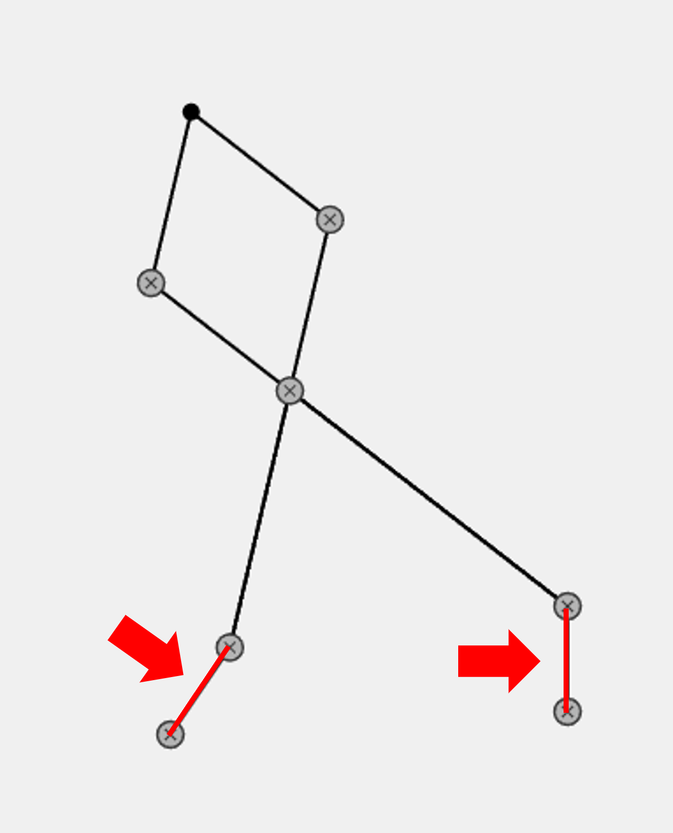
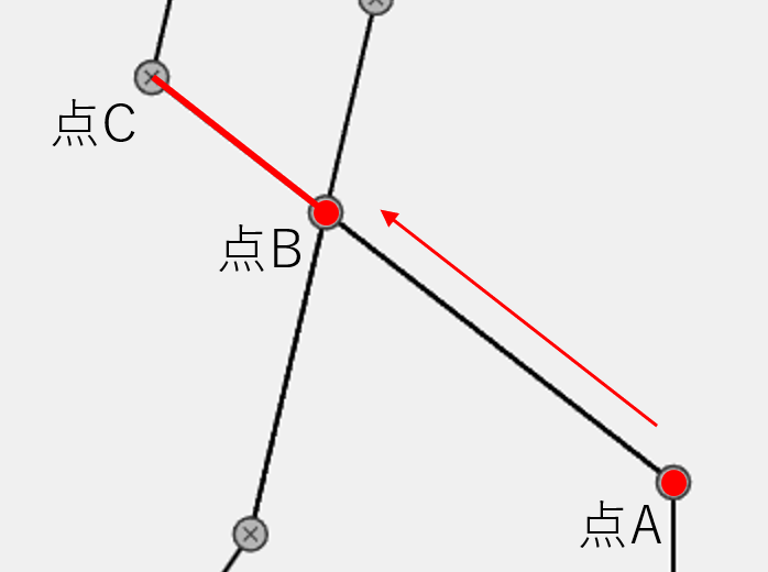
- 接点から延長される線
- 軌道を描く点
1. 回転する線を表すクラス
ロジック説明
まず軸となる、回転する線を作成します。
唯一自分で動作する部品です、中心位置・線の長さ・回転方向・速度をパラメータとして持たせています。
プログラム
別の部品と接続するため、getEndPoint()で現在の線の端っこの座標を返す機能をつけています。
/**
 * 回転する線を表すクラス
 */
class RotatingLine {
    /**
     * コンストラクタ
     * @param {number} centerX - 回転の中心X座標
     * @param {number} centerY - 回転の中心Y座標
     * @param {number} length - 線の長さ
     * @param {color} color - 線の色
     * @param {number} direction - 回転の向き(1で時計回り、-1で反時計回り)
     * @param {number} speed - 回転速度(角度の増加量)
     */
    constructor(centerX, centerY, length, color, direction, speed) {
        this.cx = centerX;
        this.cy = centerY;
        this.length = length;
        this.color = color;
        this.direction = direction;
        this.speed = speed;
        this.angle = 0;
        this.dragging = false;
        this.offsetX = 0;
        this.offsetY = 0;

        this.startDragX = centerX;
        this.startDragY = centerY;
    }

    /**
     * フレームごとの回転角度を更新
     */
    update() {
        this.angle += this.speed * this.direction;
    }

    /**
     * 回転した線をキャンバスに描画
     */
    display() {
        push();
        translate(this.cx, this.cy);
        rotate(this.angle);
        stroke(this.color);
        strokeWeight(2);
        line(0, 0, this.length, 0);
        pop();
    }

    /**
     * 線の先端(回転後の位置)を返す
     * @returns {p5.Vector} 線の先端の座標
     */
    getEndPoint() {
        let x = this.cx + cos(this.angle) * this.length;
        let y = this.cy + sin(this.angle) * this.length;
        return createVector(x, y);
    }
}
動作イメージ

2. 2点から結合される線のクラス
ロジック説明
次は、2点から結合する線を作成します。
実は交差している線は、一本の線ではなく二つの部品から構成されています。
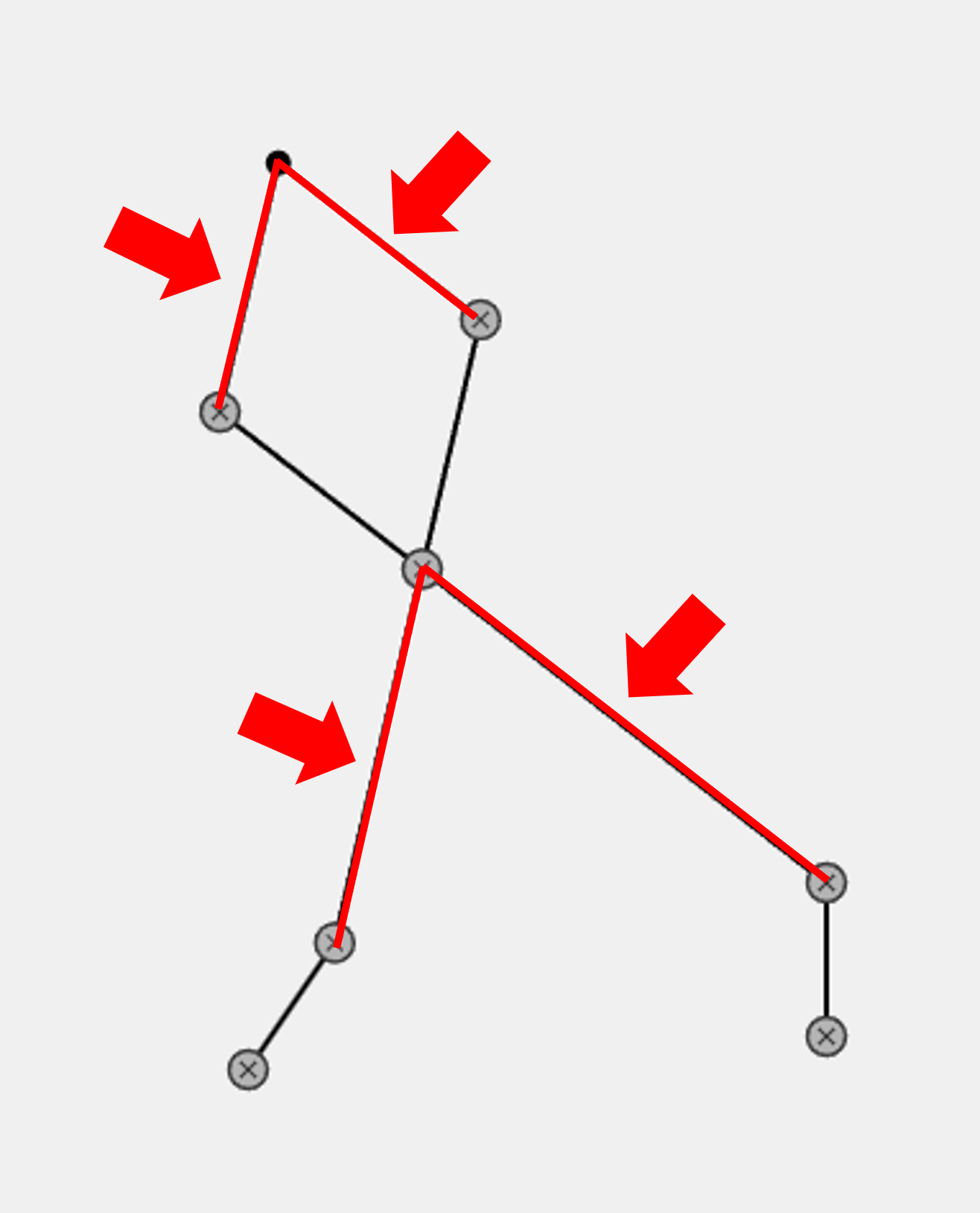
常に2点の距離が変わり続ける中で、結合する点を計算しなければなりません。
線の長さと始点の位置は指定するので、余弦定理を使って結合する点を求めます。

プログラム
実は、点Aと点Bから、作成できる三角形は二つあり、useUpperで上側か下側を指定できるようにしています。
/**
 * 2点A, Bからそれぞれ異なる長さ r1, r2 で伸ばす棒が交差する点を求める
 * @param {p5.Vector} A - 棒1の起点
 * @param {p5.Vector} B - 棒2の起点
 * @param {number} r1 - 棒1の長さ
 * @param {number} r2 - 棒2の長さ
 * @param {boolean} useUpper - trueで上側交点、falseで下側交点を返す
 * @returns {p5.Vector|null} - 交差点(上側)、なければ null
 */
function getFixedLengthJointDual(A, B, r1, r2, useUpper = true) {
    let d = dist(A.x, A.y, B.x, B.y);
    if (d > r1 + r2 || d  abs(r1 - r2) || d === 0) return null;

    let dx = (B.x - A.x) / d;
    let dy = (B.y - A.y) / d;

    // 三角形の底辺から高さ h を計算(余弦定理の派生)
    let a = (r1 * r1 - r2 * r2 + d * d) / (2 * d);
    let h = Math.sqrt(r1 * r1 - a * a);

    // 中点からのベース位置(交差線の直下)
    let px = A.x + a * dx;
    let py = A.y + a * dy;

    // 垂直ベクトル(上側を選択)
    let nx = -dy;
    let ny = dx;

    // 上側 or 下側を選んで返す
    let sign = useUpper ? 1 : -1;

    return createVector(px + sign * h * nx, py + sign * h * ny);
}
2点の交差する点を求めたときに、「交点が無い」もしくは「複数存在する」場合にnullが返ってきてしまいます。
if (d > r1 + r2 || d でエラーにならないように、部品を配置する必要があります。(こちらは別途別の記事にしようかと思います)
そしてその結果を受け取って、オブジェクト自体は、線を引いているだけで簡単です。
/**
 * 回転する線に接続する線のクラス
 */
class ConnectingLine {
    /**
     * コンストラクタ
     * @param {number} length - 線の長さ
     * @param {color} color - 線の色
     */
    constructor(length, color) {
        this.length = length;
        this.color = color;
        this.start = createVector(0, 0);
        this.end = createVector(0, 0);
    }

    update(start, end) {
        this.start = start.copy();
        this.end = end.copy();
    }

    display() {
        stroke(this.color);
        strokeWeight(2);
        line(this.start.x, this.start.y, this.end.x, this.end.y);
    }
}
動作イメージ

3. 接点から延長される線のクラス
ロジック説明
次に結合した点からの延長線を作成します。
線分ABの延長線上にC点を配置し、AからCまでを一本の直線のように見せます。
プログラム
/**
 * 任意の方向に延長する直線クラス
 */
class ExtendedLine {
    /**
     * コンストラクタ
     * @param {p5.Vector} start - 始点
     * @param {p5.Vector} direction - 向きベクトル
     * @param {number} length - 線の長さ
     * @param {color} color - 線の色
     */
    constructor(start, direction, length, color) {
        this.start = start.copy();
        this.setDirection(direction);
        this.length = length;
        this.color = color;
    }

    /**
     * 向きを更新(内部的に正規化)
     * @param {p5.Vector} direction
     */
    setDirection(direction) {
        this.direction = direction.copy().normalize();
    }

    /**
     * 始点の更新
     * @param {p5.Vector} start
     */
    setStart(start) {
        this.start = start.copy();
    }

    /**
     * 線を描画
     */
    display() {
        let end = p5.Vector.add(this.start, p5.Vector.mult(this.direction, this.length));
        stroke(this.color);
        strokeWeight(2);
        line(this.start.x, this.start.y, end.x, end.y);
    }

    /**
     * 始点と終点から向きベクトルを自動計算して更新する
     * @param {p5.Vector} start - 始点ベクトル
     * @param {p5.Vector} end - 終点ベクトル
     */
    updateFromPoints(start, end) {
        this.setStart(end);
        const direction = p5.Vector.sub(end, start);
        this.setDirection(direction);
    }

     /**
     * 線の先端(回転後の位置)を返す
     * @returns {p5.Vector} 線の先端の座標
     */
    getEndPoint() {
        return p5.Vector.add(this.start, p5.Vector.mult(this.direction, this.length));
    }
}
動作イメージ

4. 軌道を描く点する点のクラス
ロジック説明
リンク機構の軌道描くところだけではなく、関節部分も同じ部品を使っています。
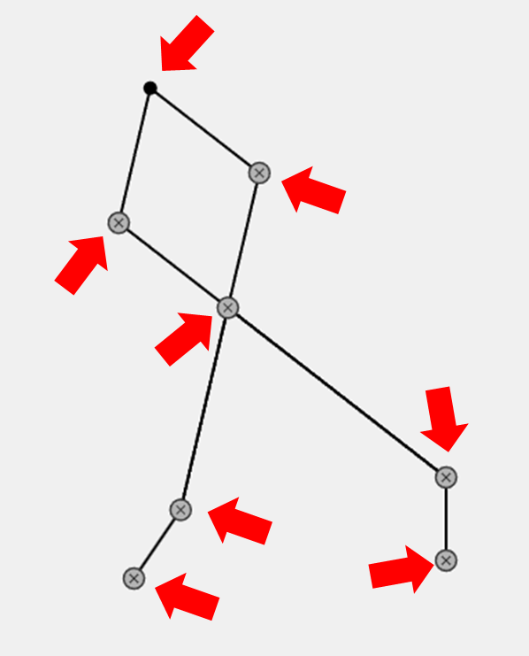
引数で、軌道の描画をするか決めており、描画しない場合はメカニック見た目にしています。
また、軌道を描く方法ですが、軌跡座標を配列に保持しています。
プログラム
/**
 * 点クラス
 */
class ConnectingPoint {
    /**
     * コンストラクタ
     * @param {number} size - 表示サイズ
     * @param {color} color - 色
     * @param {color} orbitColor - 軌道の色
     * @param {boolean} isOrbit - 軌道の描画
     */
    constructor(size, color, orbitColor, isOrbit) {
        this.pos = createVector(0, 0); // 現在位置
        this.size = size;
        this.color = color;
        this.orbitColor = orbitColor;
        this.isOrbit = isOrbit;

        this.orbit = []; // 軌跡座標
        this.orbitSave = true;
    }

    /**
     * 接続点の位置を更新し、軌跡も保存
     * @param {p5.Vector} pos - 接続点の位置
     */
    update(pos) {
        this.pos = pos.copy();
        this.orbit.push(this.pos.copy());
    }


    /**
     * 軌跡の描画
     */
    displayOrbit() {
        if (this.isOrbit && this.orbit.length > 1) {
            noFill();
            stroke(this.orbitColor);
            strokeWeight(1.5);
            beginShape();
            for (let p of this.orbit) {
                vertex(p.x, p.y);
            }
            endShape();
        }
    }

    /**
     * 点の描画
     */
    displayPoint() {
        push();
        translate(this.pos.x, this.pos.y);

        if (this.isOrbit) {
            fill(this.color);
            noStroke();
            ellipse(0, 0, this.size, this.size);
        } else {
            // ねじ風デザイン
            fill(180);
            stroke(60);
            strokeWeight(1.5);
            ellipse(0, 0, this.size+5, this.size+5);

            // 十字のドライバー溝
            stroke(60);
            strokeWeight(1);
            line(-this.size * 0.3, -this.size * 0.3, this.size * 0.3, this.size * 0.3);
            line(-this.size * 0.3, this.size * 0.3, this.size * 0.3, -this.size * 0.3);
        }

        pop();
    }
}
動作イメージ
軌道を描く点の配置は、「2. 2点から結合される線のクラス」と同様の仕組みなので説明を割愛します。

これで、目的のリンク機構が作成できました!
今回は、リンク機構の動きをシミュレーションするプログラムを作成してみました。
正直、このシミュレータがどんな役に立つかは分かりませんが、こういう「無意味だけど面白い」ものってワクワクします。
Web画面を用意しているので、回転速度や回転方向を調整して、様々な軌道を描いてみてください。
また、興味のある方は、GitHubのリポジトリを覗いてみてください。
ここまで読んで頂きありがとうございました。
Views: 1
